Logic DC Jack

This is an easy-to-use logic controller which implement logic AND and logic negation. It is designed with H Bridge which get certain drive function to drive motor and other applications, now your application will not just limited on LED applications. If you are a novice to programming and inclined to make a simple application, this will be smart choice to get something started.
Features
Dual input and single output
Select the logic via a switch
Input default to HIGH
Half bridge output, can drive motor directly
Power by 9V Battery
Specifications
No-load current: 10±1mA;
Input voltage: 6~9V;
Output voltage: 5V;
Power conversion efficiency 82±5%
Hardware Overview
Here is block diagram of Logic_DC_Jack module which consists of following parts.
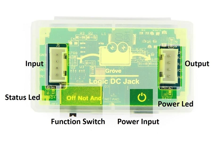
Input - Logic input
GND - Connect to ground
VCC - Connect to power supply
IN2 - Input2
IN1 - Input1
Output - Logic output
GND - Connect to ground
VCC - Connect to power supply
OUT - Output
OUT - Output
Status Led - a red led
ON - NOT Mode
- OFF - AND Mode
Function Switch
Off - Power off
Not - NOT Mode, means the board now is a NOT logic gate, it could only support one input module.
And - AND Mode, when only one Grove cable is inserted into the left socket of mainboard, the mainboard will be a simple connector. But if you used a branched Grove cable, the main board will behave like an AND logic gates
Note: When in AND Mode, IN2 is default to HIGH, so when it's only one input module, Logic DC Jack act as a buffer
Power Input - DC Power input, 6-9V is required
Power Led - A green led, on when there is power supply
Getting Started
After this section, you can make Logic DC Jack run with only few steps.
How does it work?
Logic DC Jack is a logic device, which's used to achieve some simple logic function.Please refer to these links to know something information about NOT gate and AND gate before we get started.
This module includes two type of cables and you will use one of it while plugging an input or two inputs onto the input port.
- Situation 1 – One input
- If the input is only one module, the Logic DC Jack can realize the logic function of AND and NOT. Following is the figure of logic function:

- Situation 2 – Two inputs
- If the inputs are two modules, this Logic DC Jack can only realize the logic function of AND. Following is the figure of logic function:

Choose the number of input first and then adjust the switch to a right position, the needed logic function is confirmed.
How to judge the input port and output port ?
There're two arrow seals on the shell, you can distinguish the input and output easily.

How to know the default input level ?
Even we know how to use the logic function, but how we know the default level state of the input, because different default level state can make a different output state. Here, you can get it by a simple experiment.
Preparations
Something is needed:
9V Battery
Connecting hardware
In this demo, we use Grove - Button as INPUT, and Grove - Red LED as OUTPUT.
Switch to NOT gate.
As shown below:

Review Results
As you know, only if the output level is 1, then the Grove - LED could be turned on. After power ON, you will find that Grove - LED is on, in a other word, the output level is 1 according to the figure of logic, so we can know: if the output the 1, the switch mode is NOT, so the default input level is 0.
Demo about two inputs
If you want to use two inputs, you need the Grove Branch Cable.
With this cable, you can connect 2 Grove to the INPUT. One connect to Input1 and the other to Input2.

Here is an example, 2 Buttons INPUT and a LED OUTPUT:

The led will on only when 2 buttons pressed.
Tips: This cable can also used as output, if you want to control the state level of 2 Groves at the same time, this cable is needed. Please pay attention: If using the cable by this way, the state level of two outputs is the same.Work With Lego
Logic DC Jack contain a Lego-compatible case, you can insert Logic DC Jack to Lego, make it more funny.
About the Grove Base that compatible with Lego, it's coming soon.
Here is a demo:

Compatible Groves for Logic DC Jack
Below Groves can work with Logic DC Jack well:
Input
Output
Schematic Online Viewer
Resources
- [PDF] Schematic in PDF
- [Eagle] Schematic in Eagle
- [PDF]Logic DC Jack v1.0 pdf
- [EAGLE]Logic DC Jack v1.0 sch
- [Wik] Wiki page of NOT Gate
- [Wik] Wiki page of AND Gate
Tech Support & Product Discussion
Thank you for choosing our products! We are here to provide you with different support to ensure that your experience with our products is as smooth as possible. We offer several communication channels to cater to different preferences and needs.