BLE Nitrogen

Zephyr applications use the nrf52_nitrogen configuration to run on the nRF52 Nitrogen hardware. It provides support for the Nordic Semiconductor nRF52832 ARM Cortex-M4F CPU and the following devices:
- NVIC (Nested Vectored Interrupt Controller)
- SYSTICK (System Tick System Clock)
- UART
- GPIO
- FLASH
The Nordic Semiconductor Infocenter contains the processor's information and the datasheet.
It is strongly recommended that you update your development environment with the latest SDK since new functionality is tested against the latest releases.

##Features
- nRF52832 microcontroller with 512kB Flash, 64kB ram
- Cortex M4
- BLE
- NFC
- USB power supply with fuse protect
- Battery management
- On board battery charger
- Battery connector
- Battery charge indicate LED
- LPC11U35 on board SWD debugger
- SWD debugger firmware
- USB to Uart
- Drag and Drop firmware upgrade
- Auto reset and run after firmware upgraded
- BLE power consumption measurement
- On board current measure circuit
- 1uA measurement capability
- Upto 150mA current measure
- 7 LEDs
- USR1, BT, PWR, CDC, DAP, MSD, Battery charge
- Two push buttons
- USR and RESET(also for LPC11U35 firmware upgrade)
- SWD debug connectors
- nRF52832 SWD connector
- nRF52832 Uart connector
- On board chip antenna
- 1.8V work voltage
- 2x20pin 2.0mm pitch Low speed connector
- Fully compatible with 96Boards IoT standards
##Specifications
| Parameter | Value |
|---|---|
| Chipset | nRF52832 |
| Clock Speed | 64MHz |
| Flash | 512KB |
| SRAM | 96KB |
| Digital Output Voltage | 1.8V |
| Analog Pins | 4 |
| Analog Input Voltage | 1.8V |
| Dimensions | 60x30mm |
##Hardware Overview

1.Micro USB - for debug, programming, power and battery charge.
2.LED Indicators
- USR1 - User controlled led, connected to P0.29
- BT - Bluetooth indicator. This led will light up when connect to a device.
- PWR - Light up when USB or battery inserted.
- CDC - Uart data indicator.
- DAP - SWD indicator.
- MSD - Mass Storage/Drag&Drop indicator;
3.Battery Connector - A JST-1.0 connector for 3.7V lithium battery
- Charge Indicator
- BLINK: No battery inserted
- ON: Charging
- OFF: Charged done
4.Reset Button - Press to reset the system
5.User Button - User button, connect to P0.27, pull-up
6.UART for Debug
7.BT Chip antenna
8.NFC antenna UFL connector
9.Pins - Details refer to Pin map
A.IC - NRF52832
B.IC - LPC11U35
C.IC - ETA6003
##PinMap
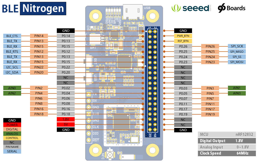
Click to view larger image.
##Sostware
###Install the Driver
Click to download the driver for Mbed.
Insert the board to PC via a micro USB cable, and double click mbedWinSerial_16466.exe to install it, then you will find a new device at your device manager.

###Advanced Guide

Schematic Online Viewer
Resources
Tech Support & Product Discussion
Thank you for choosing our products! We are here to provide you with different support to ensure that your experience with our products is as smooth as possible. We offer several communication channels to cater to different preferences and needs.