Grove - 6-Axis Accelerometer&Compass V2.0

The Grove –6-Axis Accelerometer&Compass V2.0 is a 3-axis accelerometer combined with a 3-axis magnetic sensor. It is an upgraded version of Grove - 6-Axis Accelerometer&Compass V1.0 and based on the sensor module LSM303D which has a selectable linear acceleration full scale range of ±2g / ±4g / ±8g / ±16g and a selectable magnetic field full scale range of ±2 /±4 / ±8 / ±12 gauss. Both the magnetic parts and the accelerometer parts can be powered down separately to reduce the power consumption. The Arduino can get these data via the I2C interface with the given library for this module.

Specifications
- Input Voltage: 5V
- I2C Interface and selectable SPI Interface
- Measuring scale selectable
- 6D orientation detection
- 2 independent programmable interrupt generators
- Power-down mode
- I2C Address 0x1E(default), or 0x1D
If you want to use multiplue I2C devices, please refer to [Software I2C](https://wiki.seeedstudio.com/Arduino_Software_I2C_user_guide/).
More details about Grove modules please refer to [Grove System](https://wiki.seeedstudio.com/Grove_System/)
Platforms Supported
| Arduino | Raspberry Pi |
|---|---|
|
|
The platforms mentioned above as supported is/are an indication of the module's software or theoritical compatibility. We only provide software library or code examples for Arduino platform in most cases. It is not possible to provide software library / demo code for all possible MCU platforms. Hence, users have to write their own software library.
##Hardware Overview

- ①Grove interface, connect to I2C
- ②SPI Interface
- ③I2C or SPI select pad(default is I2C), if want to use SPI, disconnect this pad
- ④Interrupt digital output
- ⑤Address select pad, default connected b and a address is 0x1E, if connect b and c address is 0x1D, if want to use SPI, disconnect this pad to either side.
Getting started
The LSM303D is a 6D sensor module that contains a 3D accelerometer and a 3D magnetic sensor. It has an I2C digital interface so that the analog to digital converter is avoided.
The MCU can collect 6D sensor data directly through the I2C interface.OK, let's start on using this LSM303D 6D sensor module.
Play with Arduino
Hardware
- Step 1. Prepare the below stuffs:
| Seeeduino V4.2 | Base Shield | Grove-6-Axis_AccelerometerAndCompass_V2.0 |
|---|---|---|
|
|
|
| Get One Now | Get One Now | Get One Now |


- Step 2. Connect Grove-6-Axis_AccelerometerAndCompass_V2 to port I2C of Grove-Base Shield.
- Step 3. Plug Grove - Base Shield into Seeeduino.
- Step 4. Connect Seeeduino to PC via a USB cable.

If we don't have Grove Base Shield, We also can directly connect this module to Seeeduino as below.
| Seeeduino_v4 | Grove-6-Axis_AccelerometerAndCompass_V2 |
|---|---|
| 5V | VCC |
| GND | GND |
| SDA | SDA |
| SCL | SCL |
Software
Step 1. Download the library from Github.
Step 2. Refer How to install library to install library for Arduino.
Step 3. Create a new Arduino sketch and paste the codes below to it or open the code directly by the path:File -> Example ->Accelerometer_Compass->Accelerometer_Compass.
Step 4. Upload the code. If you do not know how to upload the code, please check how to upload code.
Here is the code
/* LSM303DLM Example Code base on LSM303DLH example code by Jim Lindblom SparkFun Electronics

   date: 9/6/11
   license: Creative commons share-alike v3.0

   Modified by:Frankie.Chu
   Modified by:Jacky.Zhang 2014-12-11: Ported to 6-Axis Accelerometer&Compass of Seeed Studio
   Modified by:Jacky.Zhang 2015-1-6: added SPI driver

   Summary:
   Show how to calculate level and tilt-compensated heading using
   the snazzy LSM303DLH 3-axis magnetometer/3-axis accelerometer.

   Firmware:
   You can set the accelerometer's full-scale range by setting
   the SCALE constant to either 2, 4, or 8. This value is used
   in the initLSM303() function. For the most part, all other
   registers in the LSM303 will be at their default value.

   Use the write() and read() functions to write
   to and read from the LSM303's internal registers.

   Use getLSM303_accel() and getLSM303_mag() to get the acceleration
   and magneto values from the LSM303. You'll need to pass each of
   those functions an array, where the data will be stored upon
   return from the void.

   getHeading() calculates a heading assuming the sensor is level.
   A float between 0 and 360 is returned. You need to pass it a
   array with magneto values.

   getTiltHeading() calculates a tilt-compensated heading.
   A float between 0 and 360 degrees is returned. You need
   to pass this function both a magneto and acceleration array.

   Headings are calculated as specified in AN3192:
   http://www.sparkfun.com/datasheets/Sensors/Magneto/Tilt%20Compensated%20Compass.pdf
*/

/*
hardware & software comment
I2C mode:
1, solder the jumper "I2C EN" and the jumper of ADDR to 0x1E
2, use Lsm303d.initI2C() function to initialize the Grove by I2C
SPI mode:
1, break the jumper "I2C_EN" and the jumper ADDR to any side
2, define a pin as chip select for SPI protocol.
3, use Lsm303d.initSPI(SPI_CS) function to initialize the Grove by SPI
SPI.h sets these for us in arduino
const int SDI = 11;
const int SDO = 12;
const int SCL = 13;
*/

#include <LSM303D.h>
#include <Wire.h>
#include <SPI.h>

/* Global variables */
int accel[3];  // we'll store the raw acceleration values here
int mag[3];  // raw magnetometer values stored here
float realAccel[3];  // calculated acceleration values here
float heading, titleHeading;

#define SPI_CS 10

void setup()
{
    char rtn = 0;
    Serial.begin(9600);  // Serial is used for debugging
    Serial.println("\r\npower on");
    rtn = Lsm303d.initI2C();
    //rtn = Lsm303d.initSPI(SPI_CS);
    if(rtn != 0)  // Initialize the LSM303, using a SCALE full-scale range
    {
        Serial.println("\r\nLSM303D is not found");
        while(1);
    }
    else
    {
        Serial.println("\r\nLSM303D is found");
    }
}

void loop()
{
    Serial.println("\r\n**************");
    //getLSM303_accel(accel);  // get the acceleration values and store them in the accel array
    Lsm303d.getAccel(accel);
    while(!Lsm303d.isMagReady());// wait for the magnetometer readings to be ready
    Lsm303d.getMag(mag);  // get the magnetometer values, store them in mag

    for (int i=0; i<3; i++)
    {
        realAccel[i] = accel[i] / pow(2, 15) * ACCELE_SCALE;  // calculate real acceleration values, in units of g
    }
    heading = Lsm303d.getHeading(mag);
    titleHeading = Lsm303d.getTiltHeading(mag, realAccel);

    printValues();

    delay(200);  // delay for serial readability
}

void printValues()
{
    Serial.println("Acceleration of X,Y,Z is");
    for (int i=0; i<3; i++)
    {
        Serial.print(realAccel[i]);
        Serial.println("g");
    }
    //print both the level, and tilt-compensated headings below to compare
    Serial.println("The clockwise angle between the magnetic north and x-axis: ");
    Serial.print(heading, 3); // this only works if the sensor is level
    Serial.println(" degrees");
    Serial.print("The clockwise angle between the magnetic north and the projection");
    Serial.println(" of the positive x-axis in the horizontal plane: ");
    Serial.print(titleHeading, 3);  // see how awesome tilt compensation is?!
    Serial.println(" degrees");
}
Step 5. Open the serial monitor, you will see the output result of Color Sensor as shown below:

Step 6. You can see the acceleration values and the clockwise angle between the magnetic north and x-axis.
The X/Y/Z shows the 3 axis acceleration; and then the angle between the magnetic north and x-axis calculated.
And also the the angle between the magnetic north and the projection of positive x-axis calculated.
Play With Raspberry Pi
Hardware
- Step 1. Prepare the below stuffs:
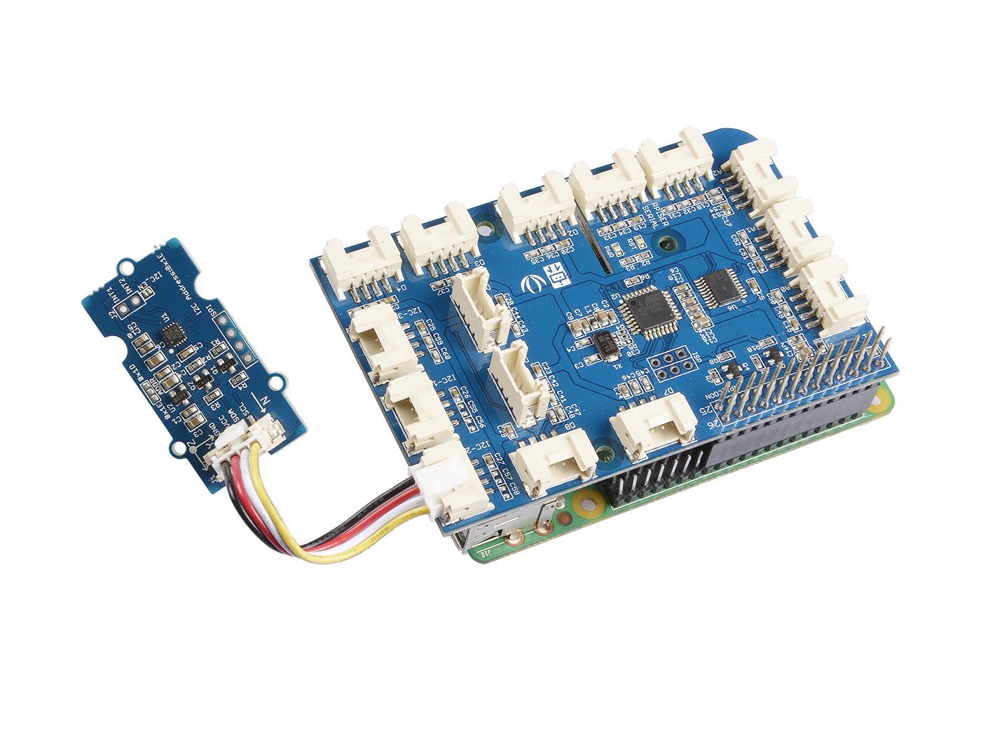
| Raspberry pi | GrovePi_Plus | Grove-6-Axis_AccelerometerAndCompass_V2.0 |
|---|---|---|
|
|
|
| Get One Now | Get One Now | Get One Now |

- Step 2. Plug the GrovePi_Plus into Raspberry.
- Step 3. Connect Grove-6-Axis_AccelerometerAndCompass_V2.0 to I2C port of GrovePi_Plus.
- Step 4. Connect the Raspberry to PC through USB cable.
Software
- Step 1. Follow Setting Software to configure the development environment.
- Step 2. Git clone the Github repository.
cd ~
git clone https://github.com/DexterInd/GrovePi.git
- Step 3. Excute below commands to use this sensor
cd ~/GrovePi/Software/Python/grove_6axis_acc_compass
python grove_6axis_accel_compass_example.py
Here is the code of example:
#!/usr/bin/env python
#
# GrovePi example for using the Grove - 6-Axis Accelerometer&Compass v2.0(https://www.seeedstudio.com/depot/Grove-6Axis-AccelerometerCompass-v20-p-2476.html)
#
# The GrovePi connects the Raspberry Pi and Grove sensors.  You can learn more about GrovePi here:  http://www.dexterindustries.com/GrovePi
#
# Have a question about this library?  Ask on the forums here:  http://forum.dexterindustries.com/c/grovepi
#
'''
## License
The MIT License (MIT)
GrovePi for the Raspberry Pi: an open source platform for connecting Grove Sensors to the Raspberry Pi.
Copyright (C) 2017  Dexter Industries
Permission is hereby granted, free of charge, to any person obtaining a copy
of this software and associated documentation files (the "Software"), to deal
in the Software without restriction, including without limitation the rights
to use, copy, modify, merge, publish, distribute, sublicense, and/or sell
copies of the Software, and to permit persons to whom the Software is
furnished to do so, subject to the following conditions:
The above copyright notice and this permission notice shall be included in
all copies or substantial portions of the Software.
THE SOFTWARE IS PROVIDED "AS IS", WITHOUT WARRANTY OF ANY KIND, EXPRESS OR
IMPLIED, INCLUDING BUT NOT LIMITED TO THE WARRANTIES OF MERCHANTABILITY,
FITNESS FOR A PARTICULAR PURPOSE AND NONINFRINGEMENT. IN NO EVENT SHALL THE
AUTHORS OR COPYRIGHT HOLDERS BE LIABLE FOR ANY CLAIM, DAMAGES OR OTHER
LIABILITY, WHETHER IN AN ACTION OF CONTRACT, TORT OR OTHERWISE, ARISING FROM,
OUT OF OR IN CONNECTION WITH THE SOFTWARE OR THE USE OR OTHER DEALINGS IN
THE SOFTWARE.
'''
import lsm303d

try:
    acc_mag=lsm303d.lsm303d()

    while True:

        # Get accelerometer values
        acc=acc_mag.getRealAccel()

        # Wait for compass to get ready
        while True:
            if acc_mag.isMagReady():
                break

        # Read the heading
        heading= acc_mag.getHeading()

        print("Acceleration of X,Y,Z is %.3fg, %.3fg, %.3fg" %(acc[0],acc[1],acc[2]))
        print("Heading %.3f degrees\n" %(heading))

except IOError:
    print("Unable to read from accelerometer, check the sensor and try again")
Here is the result:

References
Click here to know more about this parameter.


Notes
1. All ST MEMS accelerometers are factory calibrated, allowing the user to avoid any further calibration for most of the applications. However, to reach a heading accuracy of below 2°, an easy calibration procedure is needed.
2. When test The clockwise angle between the magnetic north and x-axis, you can align the device Xa axis to any direction, but do not make it face down. Refer to the below picture:

Resources
[Library] 6-Axis Accelerometer&Compass v2.0 Library for arduino
[Library] 6-Axis Accelerometer&Compass v2.0 Library for raspberry pi
[Datasheet] LSM303D_datashet
Tech Support & Product Discussion
Thank you for choosing our products! We are here to provide you with different support to ensure that your experience with our products is as smooth as possible. We offer several communication channels to cater to different preferences and needs.