Grove - 3-Axis Analog Accelerometer
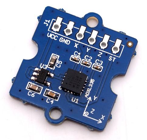
The ADXL335 is a small, thin, low power, complete 3-axis accelerometer with signal conditioned voltage outputs. The product measures acceleration with a minimum full-scale range of ±3 g. The module was designed as breakout board because ADXL335's signal is analog( more ports requested ). But the board outline is grove module that you can fix it conveniently like other groves. The sensor combined 3.3 and 5V power supply, can be used in standard Arduino device and Seeeduino Stalker. The following program code includes first-order filter which can make the output smoothly if the sensor was used in robot or toy car.

Features
- Wide power range DC3V to 5V
- Grove outline
- 3 axis sensing
- Small, low-profile package: 4×4×1.45mm LFCSP
- Low power 350µA at 3V (typical)
- High sensitive
- 10,000 g shock survival
- BW adjustment with a single capacitor per axis
- RoHS/WEEE lead-free compliant
More details about Grove modules please refer to [Grove System](https://wiki.seeedstudio.com/Grove_System/)
Application Ideas
- Motion Sensor
- Shock detector
- Vibration sensor
- Toy car
- Robot
Platforms Supported
| Arduino | Raspberry Pi |
|---|---|
|
|
The platforms mentioned above as supported is/are an indication of the module's software or theoritical compatibility. We only provide software library or code examples for Arduino platform in most cases. It is not possible to provide software library / demo code for all possible MCU platforms. Hence, users have to write their own software library.
Before usage
We suggest you to read those knowledge before using the Gas sensor, it'll help you to learn more about Arduino and our products, and also it'll let you to use open souse hardware more easier.
- Getting Started with Arduino
- What is Grove system
- Why i need a Base shield?
After reading that you will know how to use Base shield with Grove products to work well with Arduino. Let's start it !
Getting Started
The sensor's outline is breakout board, you can welding wire in the board or use jumper wire to connect the sensor.
The VCC connect to power source(DC5V or DC3.3V), GND to ground, X to Arduino analog port A0, Y to A1, Z to A2.

Download the 3-Axis Analog Accelerometer Library and Unzip it into the libraries file of Arduino IDE by the path: ..\arduino-1.0.1\libraries.
Regulate the sensor
The sensor is analog device, you should regulate the sensor before combining it with your system.
Step 1: Open the Demo: Calibration and upload it to Arduino.
Step 2: Open your serial monitor, make sure the sensor is connected. Follow the axis institutions printed on sensor's board. First, make sure that Z-axis direction is straight up, please type any character if you are ready. Change the sensor position, repeat the above operation to obtain X-axis and Y-axis direction are straight up .

Step 3: You can get the values as shown above. Please modify the macro definitions with these results in ADXL335.h

Now the calibration has been completed.
- Downloading the demo code: Measuring Acceleration, then open serial monitor, turn the sensor any angle, you can see the digital angle value sent from the accelerometer to the monitor.

Schematic Online Viewer
Resources
Project
Grove - Introduction in 3-Axis Digital Accelerometer How to use a 3-axis digital accelerometer.
Solar Panel Dual Management System (SP DMS) This IoT prototype performs two functions: 1) Theft prevention and 2) Maintenance Indication of solar panel using LinkIt ONE and Sensors.
Tech Support & Product Discussion
Thank you for choosing our products! We are here to provide you with different support to ensure that your experience with our products is as smooth as possible. We offer several communication channels to cater to different preferences and needs.