Wio LTE Cat.1

Wio Tracker (Wireless Input Output) is an open source gateway which enable faster IoT GPS solutions. It is Arduino and Grove compatible development boards that helps you track nearly any moving thing on the planet and then upload that data wirelessly. The Wio LTE is the LTE version of Wio Tracker, so now we’ve got 2 versions of Wio Tracker and the LTE (4G) version will make some differences.
There are three main updates comparing the Wio LTE to the 2G version. Firstly, from its name we know that the Wio LTE supports LTE (4G) communication which is much faster and popular than 2G. Secondly, the Wio LTE supports in total 4 different GNSS – GPS, Beidou, GLONSS and Galileo, the QZSS is also supported as bonus. With more GNSS support, positioning will be more accurate. Thirdly, the Wio LTE‘s MCU is upgraded to STM32, which is based on Cortex-M4, makes the Wio LTE 5 times faster than the 2G version. What’s more, the flash and RAM have also been raised to 1Mbytes and 192+4k bytes.
Apart from the three main updates, the LTE version is almost the same as the 2G version. If your project is using the 2G version, it would be very easy to update to the LTE version because we have prepared transplantable and expansible AT command library. The Arduino and Grove compatibility allows for quicker development through numerous libraries and a supportive community. The GPS library which will be available with the board is not just limited to Arduino – it can function just as well if you chose to develop in C/C++. With the onboard 6 Grove connections, developers can create any combination of our 180+ sensors and actuators to build project and solve any problem. Simplifying the prototyping and development phase is our goal.
The Wio LTE is well suited for outdoor projects where the device can connect to the GPS satellites and provide a real-time location of the item it is attached to. The LTE provides a wide bandwidth which allows much faster interaction between the user and device. If you are going to build projects like a bicycle sharing service, tracking pets or livestock, locating a vehicle, or even keeping track of a child, the Wio LTE is the best solution.
Please always plug 3.7V Lipo battery in case USB power supply is not sufficient.
| Product Name | How to Buy |
|---|---|
| Wio LTE JP Version |  |
| Wio LTE AU Version | |
| Wio LTE EU Version | |
| Wio LTE US Version | |
Version
| Product Version | Changes | Released Date |
|---|---|---|
| Wio Lte v1.0 | Initial | Jul 24, 2017 |
| Wio Lte v1.1 | Optimizing Production methods | Oct 18, 2017 |
| Wio Lte v1.3 | Hardware change with better power supply | March 9, 2018 |
| Wio Lte v1.3b | Adjust the layout | March 29, 2018 |
Wio Lte v1.3 Release Notes
Since the launch of this product, we have received a lot of user feedback and suggestions. We decided to further improve this product based on user feedback, so here you see, the Wio Lte v1.3 comes out.
We made some changes in the power circuit:
- Change the PMIC (Power manage IC) into MP2617, which is more stable.
- Remove the DC-DC Module which supplies for the Lte Module, instead, in this version we power the Lte Module by the main circuit or the Lipo battery.
- Add two 100uf capacitors to make the power more stable.
As you can see in the pictures below.
v1.3 v1.0


As the power circuit changes, the logic of the power indicator has also changed.
| LED Statues | Battery Statues |
|---|---|
| LED ON | Charging |
| LED off | Charging finished |
| LED Blinking | Battery error.(Including no battery statues) |
What's more, the Reset Key logic changed as well.
| Operation | Rest Range |
|---|---|
| Hold the reset button for a short time(within 2 seconds) | MCU reset/ Lte Module will not reset |
| Hold the reset button for a short time(More than 10 seconds) | The hole board will reset |
Features
- Low-cost, low-power LTE connectivity optimized for broad- band IoT applications
- Worldwide LTE and UMTS/HSPA+
- Embedded power management unit (PMU) featuring ultra-low deep-sleep current consumption
- GPS/BeiDou/GLONASS/Galileo and QZSS
- Transplantable and expansible AT Command Library for Wio Tracker
- Arduino IDE compatible
- 6 Grove Connectors
- Nano SIM and TF card 2 in 1 socket
Specification
| Item | Function | Value |
|---|---|---|
| Microcontroller | Processor | STM32F405RG, ARM 32-bit Cortex-M4, 168MHZ |
| Flash Memory | 1MB | |
| SRAM | 192+4KB | |
| Operating Voltage | 3.3V | |
| DC Current per I/O Pin | 7 mA | |
| LTE | LTE Cat.1 | AT Command: 3GPP TS27.007 and enhanced AT Commands |
| Data | LTE-FDD Max 10Mbps(DL) Max 5Mbps (UL) | |
| Protocol: TCP/UDP/PPP/FTP/HTTP/NTP/PING/QMI/HTTPS/SMTP/MMS/FTPS/SMTPS/SSL | ||
| SMS | Peer to Peer Message, SMS broadcast, Text and PDU mode | |
| Audio | Echo cancellation, Noise elimination | |
| GNSS | System | GPS/BeiDou/GLONASS/Galileo/QZSS |
| Precision | <2.5 m CEP | |
| Peripheral | Grove | 2 x Digital Port |
| 2 x Analog Port | ||
| 1 x UART | ||
| 1 x I2C | ||
| Antenna | 2 x LTE Antenna | |
| 1 x GPS Antenna | ||
| Others | USB: Power supply and upload program | |
| JST 1.0 connecter for battery | ||
| 3.5mm Audio Jack | ||
| MCU Reset Button, MCU Boot(DFU) Button,EC21 Power Button | ||
| 1 x User RGB LED SK6812 | ||
| Nano SIM and TF card 2 in 1 socket | ||
| Size | Length | 54.7mm |
| Width | 48.2mm | |
| Weight | 18g |
Power Consumption
| Status | Current | Voltage |
|---|---|---|
| Normal boot(boot moment) | 700mA | 5V |
| After boot(IDLE mode) | 300mA | 5V |
| After the boot, the normal communication status (network transmission function) | 600mA or so, the peak reaches 2A | 5V |
| Call and SMS(signal better) | 100-300mA | 5V |
| Deep sleep mode, turn off all functions, require external wake-up (wake only by Reset) | 300uA | 4.2V |
| MCU Deep Sleep mode, wake-up pin connected to module, wake-up via module | over 300uA (requires testing) | 4.2V |
There are two working conditions. One is power from 5V usb supply. The other is from 4.2v battery supply.
Application Ideas
- Pedometer
- Smart ski
- Smart two-wheeler
- Sharing bicycle
- Pet tracking machine
- Children location watch
- Smart watch
- Transportation location system
- Vehicle location system
- Property safety
Use Grove modules to expand your application. There are 6 Grove connects on board. If this is your first time to hear about Grove, please put had on [Grove System](https://wiki.seeedstudio.com/Grove_System/) for more details. In brief, Groves is hundreds of sensor that in standard style, which is consist of sensors, actuators, displays as well as communication.
Hardware Overview
![]()
![]()
If you want to use the on-board Grove connector, please use digitalWrite(B10, HIGH) to open 3V3_B. except D38 power on by default. Otherwise you can't provide power to Grove modules.
EC21 Module
EC21 contains 9 variants: EC21-E, EC21-A, EC21-V, EC21-AUT, EC21-AUV, EC21-AU, EC21-KL, EC21-J and EC21-CEL. This makes it backward-compatible with existing EDGE and GSM/GPRS networks, ensuring that it can easily migrate from LTE to 2G or 3G networks.
And EC21-A is what we are using in WIO Tracker - LTE, which supports AT&T and T-mobile sim card. If you want to customize EC21 Module for other region, feel free to email us: [email protected]
| Frequency | EC21-E | EC21-A | EC21-V | EC21-AUT | |
|---|---|---|---|---|---|
| LTE | FDD-LTE | B1/ B3/ B5/ B7/ B8/ B20 | B2/ B4/ B12 | B4/ B13 | B1/ B3/ B5/ B7/ B28 |
| TDD-LTE | |||||
| 3G | WCDMA | B1/ B5/ B8 | B2/ B4/ B5 | B1/ B5 | |
| GSM/EDGE | B3/ B8 | ||||
| Embedded GNSS | Optional | Optional | Optional | Optional | |
| Wi-Fi Interface | Y | Y | Y | Y | |
| Region | EMEA, Korea, Thailand, India | North America | North America | Australia | |
| Certification | CE/ GCF/ Vodafone | FCC/ PTCRB/ AT&T/ IC/ ROGERS | FCC/ GCF/ Verizon | RCM/ Telstra | |
| Frequency | EC21-AUV | EC21-AU | EC21-KL | EC21-J | EC20-CEL | |
|---|---|---|---|---|---|---|
| LTE | FDD-LTE | B1/ B3/ B5/ B8/ B28 | B1/ B2①/ B3/ B4/ B5/ B7/ B8/ B28 | B1/ B3/ B5/ B7/ B8 | B1/ B3/ B8/ B18/ B19/ B26 | B1/ B3/ B5 |
| TDD-LTE | B40 | |||||
| 3G | WCDMA | B1/ B5/ B8 | B1/ B2/ B5/ B8 | |||
| GSM/EDGE | Quad-band | |||||
| Embedded GNSS | N | Optional | N | N | N | |
| Wi-Fi Interface | Y | Y | Y | Y | Y | |
| Region | Vodafone Australia | South America, ANZ, Taiwan | Korea | Japan | China Telecom | |
| Certification | RCM | RCM/ Anatel/ NCC | KC/ SKT/KT*/ LGU+* | JATE/ TELEC/ DOCOMO* | CCC/ SRRC/ NAL | |
Getting Started
Install USB driver
Windows Users: Most versions of Windows won't automatically load the built-in driver for USB com ports. You'll have to download ST's USB driver STM32 Virtual COM Port Driver.
Mac OS X and Chromebook Users: The board will just plug in and work, without drivers!
Change DFU driver
For windows users:
- Step 1. Press and hold BOOT button and connect to computer you will see STM32 Device in DFU Mode at device manager as below.

- Step 2. This says that you need to use zadig_xx.exe to change DFU driver from STTub30 to WinUSB as below. If we can't see any info on the Zadig, please click Options--> List All Devices, then select STM32 Virtual COM Ports.

- Step 3. You will see the "STMicroelectronics Virtual COM Port" on device manager as below.

Play with Arduino
1. Software Configuration
- Step 1. Install Arduino IDE, recommand IDE version upon 1.8.0.
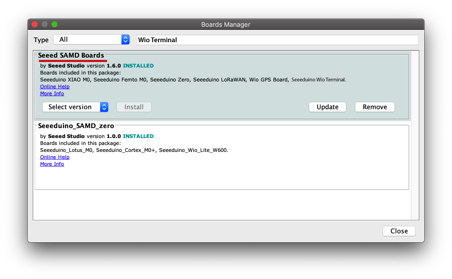
- Step 2. Follow How to Add Seeed boards to Arduino IDE to add Wio_LTE into arduino board manager.
Hi, the board of "Wio LTE Cat.1" is stored in "Seeed SAMD Boards" package like "Wio Terminal". You can refer to here to install the package.
- Step 3. Download the Wio_LTE Library from Github.
- Step 4. Refer How to install library to install library for Arduino.
2. Play with SMS Send
- Step 1. Plug the Nano SIM card into Nano SIM slot, near PCB board side.
- Step 2. Select File--> Examples-->Wio_LTE_Arduino_Library-->SMSSend sketch.
- Step 3. Change the phone number and info.
- Step 4. Press and hold BOOT button at back side of the Wio LTE and plug the USB to PC.
- Step 5. We will see STM BOOTLARDER in device manager.
- Step 6. Select Tools-->Boards-->Wio_Tracker_LTE.
- Step 7. Keep COM Port blank.
- Step 8. Select Sketch-->Upload to upload the code to Wio_LTE.
- Step 9. Press RST button to enable the COM port.
#include "wio_tracker.h"

char message[128] = "Hello from Wio Traker!";

WioTracker wio = WioTracker();

void setup() {
  wio.Power_On();
  SerialUSB.println("Power On!");

  if(!wio.waitForNetworkRegister())
  {
    SerialUSB.println("Network error!");
    return;
  } else {
    SerialUSB.println("Network ready!");
  }

  // Change xxxxxxxxxxx to your test phone number
  if(wio.sendSMS("185XXX26402", message))
  {
    SerialUSB.println("Send OK!");
  }
  else
  {
    SerialUSB.println("Send Error!");
  }

}

void loop() {
  AT_bypass();
}
- Step 10.Use COM monitor tools to print the serial message. Please do not use Arduino IDE COM monitor! That may cause the next time downloading fail, but reopen Arduino IDE can recover that issue.
- Step 11. The phone number owner will receive the message.
Power On!


Network ready!


Send OK!
3. Play with SMS Read
- Step 1. Plug the Nano SIM card into Nano SIM slot, near PCB board side.
- Step 2. Select File--> Examples-->Wio_LTE_Arduino_Library-->SMSRead sketch.
- Step 3. Press and hold BOOT button at back side of the Wio LTE and plug the USB to PC.
- Step 4. We will see STM BOOTLARDER in device manager.
- Step 5. Select Tools-->Boards-->Wio_Tracker_LTE.
- Step 6. Keep COM Port blank.
- Step 7. Select Sketch-->Upload to upload the code to Wio_LTE.
- Step 8. Press RST button to enable the COM port.
#include "wio_tracker.h"

uint16_t newSMSNumber = -1;
char message[128];
char phone[32];
char dateTime[32];


WioTracker wio = WioTracker();

void setup() {
  wio.Power_On();
  SerialUSB.println("Power On!");
  SerialUSB.println("Wait for network registered...");

  if(!wio.waitForNetworkRegister())
  {
    SerialUSB.println("Network error!");
    return;
  } else {
    SerialUSB.println("Network ready!");
  }
  wio.readAllRecUnreadSMS();  // Set all "REC UNREAD SMS" to "REC READ SMS"
}

void loop() {
  int id = wio.detectRecUnreadSMS();
  if(-1 != id){
    newSMSNumber = id;
    wio.readSMS(newSMSNumber, message, 128, phone, dateTime);
    SerialUSB.println("++++++++++++++ Start +++++++++++++++++");
    SerialUSB.print("From: ");
    SerialUSB.println(phone);
    SerialUSB.print("Date: ");
    SerialUSB.println(dateTime);
    SerialUSB.println(message);
    SerialUSB.println("++++++++++++++++ End +++++++++++++++");
  } else {
    SerialUSB.println("Waiting for new SMS!");
  }

  delay(1000);
}
- Step 9.Use COM monitor tools to print the serial message. Please do not use Arduino IDE COM monitor! That may cause the next time downloading fail, but reopen Arduino IDE can recover that issue.
- Step 10. Open serial monitor, when seeing Waitting for new SMS!, send message to the board, the new message will display soon with phone number, time, content.
Power On!
Wait for network registered...


Network ready!


Waiting for new SMS!
Waiting for new SMS!
Waiting for new SMS!

++++++++++++++ Start +++++++++++++++++
From: 1375002xxxx
Date: 17/12/20,17:40:38+32
Hello tracker
++++++++++++++++ End +++++++++++++++
Waiting for new SMS!
Waiting for new SMS!
4. Play with GPS
- Step 1. Plug the Nano SIM card into Nano SIM slot, near PCB board side.
- Step 2. Select File--> Examples-->Wio_LTE_Arduino_Library-->GNNS-->GNSS_Show_Coordinate sketch.
- Step 3. Press and hold BOOT button at back side of the Wio LTE and plug the USB to PC.
- Step 4. We will see STM BOOTLARDER in device manager.
- Step 5. Select Tools-->Boards-->Wio_Tracker_LTE.
- Step 6. Keep COM Port blank.
- Step 7. Select Sketch-->Upload to upload the code to Wio_LTE.
- Step 8. Press RST button to enable the COM port.
#include "gnss.h"


GNSS gnss = GNSS();

void setup() {
  gnss.Power_On();
  while(false == gnss.Check_If_Power_On()){
    SerialUSB.println("Waitting for module to alvie...");
    delay(1000);
  }
  SerialUSB.println("\n\rPower On!");

  if(!(gnss.open_GNSS())){
    SerialUSB.println("\n\rGNSS init failed!");
    return;
  }

  SerialUSB.println("Open GNSS OK.");
  delay(2000);
}

void loop() {
  if(gnss.getCoordinate()){
    SerialUSB.println();
    SerialUSB.print("GNSS: \r\n");

    // Output double type
    SerialUSB.print("Data type in double: ");
    SerialUSB.print(gnss.longitude, 6);
    SerialUSB.print(",");
    SerialUSB.println(gnss.latitude, 6);

    // Output char* type
    SerialUSB.print("Data type in string: ");
    SerialUSB.print(gnss.str_longitude);
    SerialUSB.print(",");
    SerialUSB.println(gnss.str_latitude);
  } else{
    SerialUSB.print("...");
  }
}
- Step 9.Use COM monitor tools to print the serial message. Please do not use Arduino IDE COM monitor! That may cause the next time downloading fail, but reopen Arduino IDE can recover that issue.
- Step 10. We will see lat, lon info printed on screen.
Waitting for module to alvie...
Waitting for module to alvie...
Waitting for module to alvie...

RDY
AT

OK


Power On!


Open GNSS OK.
.................................
GNSS:
Data type in double: 113.966255,22.583820
Data type in string: 113.966255,22.583819

GNSS:
Data type in double: 113.966248,22.583818
Data type in string: 113.966248,22.583818

GNSS:
Data type in double: 113.966248,22.583817
Data type in string: 113.966248,22.583816

GNSS:
Data type in double: 113.966248,22.583820
Data type in string: 113.966248,22.583819
5. Play with GPS in NMEA mode
- Step 1. Plug the Nano SIM card into Nano SIM slot, near PCB board side.
- Step 2. Select File--> Examples-->Wio_LTE_Arduino_Library-->GNNS-->GNSS_NMEA sketch.
- Step 3. Press and hold BOOT button at back side of the Wio LTE and plug the USB to PC.
- Step 4. We will see STM BOOTLARDER in device manager.
- Step 5. Select Tools-->Boards-->Wio_Tracker_LTE.
- Step 6. Keep COM Port blank.
- Step 7. Select Sketch-->Upload to upload the code to Wio_LTE.
- Step 8. Press RST button to enable the COM port.
#include "gnss.h"


char nmea_sentence[192];
char nmea_GSV_sentence[512];
GNSS gnss = GNSS();

void setup() {
  gnss.Power_On();
  while(false == gnss.Check_If_Power_On()){
    SerialUSB.println("Waitting for module to alvie...");
    delay(1000);
  }
  SerialUSB.println("\n\rPower On!");

  if(!(gnss.open_GNSS())){
    SerialUSB.println("\n\rGNSS init failed!");
    return;
  }
  SerialUSB.println("Open GNSS OK.");
  gnss.enable_NMEA_mode();  // Set output sentence in NMEA mode
}

void loop() {
  clean_buffer(nmea_sentence, 192);
  gnss.read_NMEA(GGA, nmea_sentence);
  SerialUSB.print(nmea_sentence);

  clean_buffer(nmea_sentence, 192);
  gnss.read_NMEA(RMC, nmea_sentence);
  SerialUSB.print(nmea_sentence);

  clean_buffer(nmea_sentence, 192);
  gnss.read_NMEA(GSA, nmea_sentence);
  SerialUSB.print(nmea_sentence);

  clean_buffer(nmea_sentence, 192);
  gnss.read_NMEA(VTG, nmea_sentence);
  SerialUSB.print(nmea_sentence);

  clean_buffer(nmea_GSV_sentence, 512);
  gnss.read_NMEA_GSV(nmea_sentence);
  SerialUSB.print(nmea_sentence);

  SerialUSB.println("\r\n");

  delay(1000);
}
- Step 9.Use COM monitor tools to print the serial message. Please do not use Arduino IDE COM monitor! That may cause the next time downloading fail, but reopen Arduino IDE can recover that issue.
- Step 10. We will see below logs.
Waitting for module to alvie...
Waitting for module to alvie...
Waitting for module to alvie...
Waitting for module to alvie...


Power On!


Open GNSS OK.

$GPRMC,,V,,,,,,,,,,N*53
$GPGSA,A,1,,,,,,,,,,,,,,,*1E
$GPVTG,,T,,M,,N,,K,N*2C
$GPGSV,3,1,12,16,60,324,40,27,54,171,40,03,19,253,,08,21,198,*7B
$GPGSV,3,2,12,09,02,322,,14,32,147,,21,04,080,,22,17,233,*7E
$GPGSV,3,3,12,23,32,314,,26,45,018,,31,35,073,,32,10,149,*7C


$GPGGA,,,,,,0,,,,,,,,*66
$GPRMC,,V,,,,,,,,,,N*53
$GPGSA,A,1,,,,,,,,,,,,,,,*1E
$GPVTG,,T,,M,,N,,K,N*2C
$GPGSV,3,1,12,03,19,253,38,08,21,198,34,14,32,147,37,16,60,324,42*70
$GPGSV,3,2,12,22,17,233,37,23,32,314,38,26,45,018,40,27,54,171,44*7D
$GPGSV,3,3,12,31,35,073,40,09,02,322,,21,04,080,,32,10,149,*75


$GPGGA,,,,,,0,,,,,,,,*66
$GPRMC,,V,,,,,,,,,,N*53
$GPGSA,A,1,,,,,,,,,,,,,,,*1E
$GPVTG,,T,,M,,N,,K,N*2C
$GPGSV,4,1,13,03,19,253,40,04,,,37,08,21,198,36,09,02,322,33*43
$GPGSV,4,2,13,14,32,147,37,16,60,324,41,22,17,233,40,23,32,314,39*72
$GPGSV,4,3,13,26,45,018,41,27,54,171,41,31,35,073,40,21,04,080,*78
$GPGSV,4,4,13,32,10,149,*47


$GPGGA,,,,,,0,,,,,,,,*66
$GPRMC,,V,,,,,,,,,,N*53
$GPGSA,A,1,,,,,,,,,,,,,,,*1E
$GPVTG,,T,,M,,N,,K,N*2C
$GPGSV,4,1,14,03,19,253,39,04,,,37,08,21,198,36,09,02,322,34*4D
$GPGSV,4,2,14,14,32,147,36,16,60,324,41,22,17,233,37,23,32,314,39*74
$GPGSV,4,3,14,26,45,018,41,27,54,171,41,31,35,073,41,21,04,080,*7E
$GPGSV,4,4,14,32,10,149,,33,,,34*47
$GPVTG,,T,,M,,N,,K,N*2C


$GPGGA,110917.30,2235.028403,N,11357.974736,E,1,10,0.9,52.2,M,-1.0,M,,*43
$GPRMC,110917.30,A,2235.028403,N,11357.974736,E,0.0,,050118,2.3,W,A*0B
$GPGSA,A,3,03,08,09,14,16,22,23,26,27,31,,,1.8,0.9,1.6*37
$GPVTG,,T,2.3,M,0.0,N,0.0,K,A*0C
$GPGSV,4,1,15,03,19,253,38,04,,,36,08,21,198,34,09,02,322,33*49
$GPGSV,4,2,15,14,32,147,36,16,60,324,40,22,17,233,36,23,32,314,38*74
$GPGSV,4,3,15,26,45,018,40,27,54,171,40,31,35,073,40,21,04,080,*7E
$GPGSV,4,4,15,32,10,149,,33,,,34,46,,,34*43
$GPVTG,,T,2.3,M,0.0,N,0.0,K,A*0C
6. Play with Call out
- Step 1. Plug the Nano SIM card into Nano SIM slot, near PCB board side.
- Step 2. Select File--> Examples-->Wio_LTE_Arduino_Library-->Callup sketch.
- Step 3. Change the phone number.
- Step 4. Press and hold BOOT button at back side of the Wio LTE and plug the USB to PC.
- Step 5. We will see STM BOOTLARDER in device manager.
- Step 6. Select Tools-->Boards-->Wio_Tracker_LTE.
- Step 7. Keep COM Port blank.
- Step 8. Select Sketch-->Upload to upload the code to Wio_LTE.
- Step 9. Press RST button to enable the COM port.
- Step 10.Use COM monitor tools to print the serial message. Please do not use Arduino IDE COM monitor! That may cause the next time downloading fail, but reopen Arduino IDE can recover that issue.
- Step 11. The phone number owner will receive the call.
#include "wio_tracker.h"

WioTracker wio = WioTracker();

void setup() {
  wio.Power_On();
  SerialUSB.println("Power On!");

  while(!wio.init()){
    delay(1000);
    SerialUSB.println("Accessing network...");
  }
  SerialUSB.println("Initialize done...");

  bool ret = wio.waitForNetworkRegister();
  if(true == ret){
      SerialUSB.println("Network accessed!");
  }else {
      SerialUSB.println("Network failed!");
      return;
  }

  // Make a phone call
  wio.callUp("185XXX26402");
  SerialUSB.println("Calling...");

}

void loop() {
  /* Debug */
  AT_bypass();
}
7. Play with Socket TCP/UDP client
- Step 1. Plug the Nano SIM card into Nano SIM slot, near PCB board side.
- Step 2. Select File--> Examples-->Wio_LTE_Arduino_Library-->TCPConnect.
- Step 3. Change the phone number.
- Step 4. Press and hold BOOT button at back side of the Wio LTE and plug the USB to PC.
- Step 5. We will see STM BOOTLARDER in device manager.
- Step 6. Select Tools-->Boards-->Wio_Tracker_LTE.
- Step 7. Keep COM Port blank.
- Step 8. Select Sketch-->Upload to upload the code to Wio_LTE.
#include "ethernet.h"

Ethernet eth = Ethernet();


// const char apn[10] = "CMNET";
const char apn[10] = "UNINET";
const char URL[100] = "mbed.org";
char http_cmd[100] = "GET /media/uploads/mbed_official/hello.txt HTTP/1.0\n\r\n\r";
int port = 80;

int ret = 0;


void setup() {
  SerialUSB.println("Begin...");
  eth.Power_On();
  while(false == eth.Check_If_Power_On()){
    SerialUSB.println("Waitting for module to alvie...");
    delay(1000);
  }

  while(!eth.init()){
    delay(1000);
    SerialUSB.println("Accessing network...");
  }
  SerialUSB.println("Initialize done...");

  eth.join(apn);
  SerialUSB.print("\n\rIP: ");
  SerialUSB.print(eth.ip_string);

  if(eth.connect(URL, port, TCP))
  {
    eth.write(http_cmd);
    while(MODULE_PORT.available()){
        serialDebug.write(MODULE_PORT.read());
    }
    eth.close(1);
  }
  else {
    SerialUSB.println("Connect Error!");
  }

}

void loop() {
  /* Debug */
  AT_bypass();
}
- Step 9. Press RST button to enable the COM port.
- Step 10.Use COM monitor tools to print the serial message. Please do not use Arduino IDE COM monitor! That may cause the next time downloading fail, but reopen Arduino IDE can recover that issue.
Begin...
Waitting for module to alvie...
Waitting for module to alvie...
Waitting for module to alvie...


Initialize done...


IP: 10.229.226.108


+QIURC: "recv",0,389
HTTP/1.1 200 OK
Server: nginx/1.11.12
Date: Mon, 25 Dec 2017 04:45:01 GMT
Content-Type: text/plain
Content-Length: 14
Connection: close
Last-Modified: Fri, 27 Jul 2012 13:30:34 GMT
Accept-Ranges: bytes
Cache-Control: max-age=36000
Expires: Mon, 25 Dec 2017 14:44:58 GMT
X-Upstream-L1-next-hop: 217.140.101.22:8080
X-Upstream-L1: developer-sjc-cyan-border-nginx

Hello world!


+QIURC: "closed",0
8. Play with SD Card
Epruino firmware v1.94 is not support SD card drive, please use v1.96 or later, the latest version is v1.99.
- Step 1. Plug micro SD card to the SD card slot.
- Step 2. Select File--> Examples-->Wio_LTE_Arduino_Library-->SDCard->CardInfo.
- Step 3. Change the phone number.
- Step 4. Press and hold BOOT button at back side of the Wio LTE and plug the USB to PC.
- Step 5. We will see STM BOOTLARDER in device manager.
- Step 6. Select Tools-->Boards-->Wio_Tracker_LTE.
- Step 7. Keep COM Port blank.
- Step 8. Select Sketch-->Upload to upload the code to Wio_LTE.
 // include the SD library:
#include <SD.h>

// set up variables using the SD utility library functions:
Sd2Card card;
SdVolume volume;
SdFile root;

const int chipSelect = 43;

void setup()
{

  SerialUSB.print("\nInitializing SD card...");
  pinMode(SS, OUTPUT);


  // we'll use the initialization code from the utility libraries
  // since we're just testing if the card is working!
  while (!card.init(SPI_HALF_SPEED, chipSelect)) {
    SerialUSB.println("initialization failed. Things to check:");
    SerialUSB.println("* is a card is inserted?");
    SerialUSB.println("* Is your wiring correct?");
    SerialUSB.println("* did you change the chipSelect pin to match your shield or module?");
  }

  // print the type of card
  SerialUSB.print("\nCard type: ");
  switch(card.type()) {
    case SD_CARD_TYPE_SD1:
      SerialUSB.println("SD1");
      break;
    case SD_CARD_TYPE_SD2:
      SerialUSB.println("SD2");
      break;
    case SD_CARD_TYPE_SDHC:
      SerialUSB.println("SDHC");
      break;
    default:
      SerialUSB.println("Unknown");
  }

  // Now we will try to open the 'volume'/'partition' - it should be FAT16 or FAT32
  if (!volume.init(card)) {
    SerialUSB.println("Could not find FAT16/FAT32 partition.\nMake sure you've formatted the card");
    return;
  }


  // print the type and size of the first FAT-type volume
  uint32_t volumesize;
  SerialUSB.print("\nVolume type is FAT");
  SerialUSB.println(volume.fatType(), DEC);
  SerialUSB.println();

  volumesize = volume.blocksPerCluster();    // clusters are collections of blocks
  volumesize *= volume.clusterCount();       // we'll have a lot of clusters
  volumesize *= 512;                            // SD card blocks are always 512 bytes
  SerialUSB.print("Volume size (bytes): ");
  SerialUSB.println(volumesize);
  SerialUSB.print("Volume size (Kbytes): ");
  volumesize /= 1024;
  SerialUSB.println(volumesize);
  SerialUSB.print("Volume size (Mbytes): ");
  volumesize /= 1024;
  SerialUSB.println(volumesize);


  SerialUSB.println("\nFiles found on the card (name, date and size in bytes): ");
  root.openRoot(volume);

  // list all files in the card with date and size
  root.ls(LS_R | LS_DATE | LS_SIZE);
}


void loop(void) {

}
- Step 9. Press RST button to enable the COM port.
- Step 10.Use COM monitor tools to print the serial message. Please do not use Arduino IDE COM monitor! That may cause the next time downloading fail, but reopen Arduino IDE can recover that issue.
Initializing SD card...
Card type: SDHC

Volume type is FAT32

Volume size (bytes): 2689048576
Volume size (Kbytes): 2626024
Volume size (Mbytes): 2564

Files found on the card (name, date and size in bytes):
9. Play with Grove Module
9.1 Play with Grove Digital Module
We use Grove-TemperatureAndHumidity_Sensor as digital input and connect to D20 of Wio LTE.
- Step 1. Press and hold BOOT button at back side of the Wio LTE and plug the USB to PC.
- Step 2. We will see STM BOOTLARDER in device manager.
- Step 3. Select Tools-->Boards-->Wio_Tracker_LTE.
- Step 4. Keep COM Port blank.
- Step 5. Download WioLTEforArduino Library and Grove-TemperatureAndHumidity_Sensor Library from Github. Refer How to install library to install library for Arduino.
- Step 6. Copy below code to Sketch.
- Step 7. Click Upload to upload the code to Wio_LTE.
#include <WioLTEforArduino.h>
#include "DHT.h"
#define DHTPIN  (WIOLTE_D20)
#define INTERVAL    (100)

// Uncomment whatever type you're using!
#define DHTTYPE DHT11   // DHT 11
//#define DHTTYPE DHT22   // DHT 22  (AM2302)
//#define DHTTYPE DHT21   // DHT 21 (AM2301)

WioLTE Wio;
DHT dht(DHTPIN, DHTTYPE);

void setup()
{
  delay(200);
  SerialUSB.println("### I/O Initialize.");
  Wio.Init();
  SerialUSB.println("### Power supply ON.");
  Wio.PowerSupplyGrove(true);
  delay(500);
  SerialUSB.println("### Initial temperature and humidity sensor.");
  dht.begin();
}

void loop()
{
    // Reading temperature or humidity takes about 250 milliseconds!
    // Sensor readings may also be up to 2 seconds 'old' (its a very slow sensor)
    float h = dht.readHumidity();
    float t = dht.readTemperature();

    // check if returns are valid, if they are NaN (not a number) then something went wrong!
    if (isnan(t) || isnan(h))
    {
        SerialUSB.println("Failed to read from DHT");
    }
    else
    {
        SerialUSB.print("Humidity: ");
        SerialUSB.print(h);
        SerialUSB.print(" %\t");
        SerialUSB.print("Temperature: ");
        SerialUSB.print(t);
        SerialUSB.println(" *C");
    }
}
- Step 8. Press RST button to enable the COM port.
- Step 9. Use COM monitor tools to print the serial message. Please do not use Arduino IDE COM monitor! That may cause the next time downloading fail, but reopen Arduino IDE can recover that issue.
### I/O Initialize.
### Power supply ON.
### Initial temperature and humidity sensor.
Humidity: 40.00 %   Temperature: 27.00 *C
Humidity: 40.00 %   Temperature: 27.00 *C
Humidity: 40.00 %   Temperature: 27.00 *C
Humidity: 40.00 %   Temperature: 27.00 *C
Humidity: 39.00 %   Temperature: 27.00 *C
9.2 Play with Grove Analog Module
We use Grove-Light Sensor as analog input and connect to A4 of Wio LTE(12bit ADC).
- Step 1. Press and hold BOOT button at back side of the Wio LTE and plug the USB to PC.
- Step 2. We will see STM BOOTLARDER in device manager.
- Step 3. Select Tools-->Boards-->Wio_Tracker_LTE.
- Step 4. Keep COM Port blank.
- Step 5. Download WioLTEforArduino Library from Github. Refer How to install library to install library for Arduino.
- Step 6. Copy below code to Sketch.
- Step 7. Click Upload to upload the code to Wio_LTE.
#include <WioLTEforArduino.h>
#define LIGHT_PIN  (WIOLTE_A4)
WioLTE Wio;

void setup() {
  delay(200);
  SerialUSB.println("### I/O Initialize.");
  Wio.Init();
  SerialUSB.println("### Power supply ON.");
  Wio.PowerSupplyGrove(true);
  delay(500);
  SerialUSB.println("### Setup pin mode.");
  pinMode(LIGHT_PIN, INPUT_ANALOG);
}

void loop() {
  int light = analogRead(LIGHT_PIN);
  SerialUSB.println(light);
  delay(1000);
}
- Step 8. Press RST button to enable the COM port.
- Step 9. Use COM monitor tools to print the serial message. Please do not use Arduino IDE COM monitor! That may cause the next time downloading fail, but reopen Arduino IDE can recover that issue.
### I/O Initialize.
### Power supply ON.
### Setup pin mode.
2531
2530
2530
2530
2531
2533
2532
2531
9.3 Play with Grove I2C Module
We use Grove - 3-Axis Digital Accelerometer(±16g) as I2C device and connect to I2C port of Wio LTE.
- Step 1. Press and hold BOOT button at back side of the Wio LTE and plug the USB to PC.
- Step 2. We will see STM BOOTLARDER in device manager.
- Step 3. Select Tools-->Boards-->Wio_Tracker_LTE.
- Step 4. Keep COM Port blank.
- Step 5. Download WioLTEforArduino Library and ADXL345 from Github. Refer How to install library to install library for Arduino.
- Step 6. Copy below code to Sketch.
- Step 7. Click Upload to upload the code to Wio_LTE.
#include <WioLTEforArduino.h>
#include <ADXL345.h>

#define INTERVAL    (100)

WioLTE Wio;
ADXL345 Accel;

void setup()
{
  delay(200);
  SerialUSB.println("### I/O Initialize.");
  Wio.Init();
  SerialUSB.println("### Power supply ON.");
  Wio.PowerSupplyGrove(true);
  delay(500);
  Accel.powerOn();
  SerialUSB.println("### Setup completed.");
}

void loop()
{
  int x;
  int y;
  int z;
  Accel.readXYZ(&x, &y, &z);
  SerialUSB.print(x);
  SerialUSB.print(' ');
  SerialUSB.print(y);
  SerialUSB.print(' ');
  SerialUSB.println(z);
  delay(INTERVAL);
}
- Step 8. Press RST button to enable the COM port.
- Step 9. Use COM monitor tools to print the serial message. Please do not use Arduino IDE COM monitor! That may cause the next time downloading fail, but reopen Arduino IDE can recover that issue.
### I/O Initialize.
### Power supply ON.
### Setup completed.
-224 -51 -82
-227 -40 -90
-231 -37 -91
-229 -37 -90
-227 -38 -90
-229 -39 -90
9.4 Play with Grove UART Module
We use Grove-CO2 as UART device and connect to UART port of Wio LTE.
- Step 1. Press and hold BOOT button at back side of the Wio LTE and plug the USB to PC.
- Step 2. We will see STM BOOTLARDER in device manager.
- Step 3. Select Tools-->Boards-->Wio_Tracker_LTE.
- Step 4. Keep COM Port blank.
- Step 5. Download WioLTEforArduino Library from Github. Refer How to install library to install library for Arduino.
- Step 6. Copy below code to Sketch.
- Step 7. Click Upload to upload the code to Wio_LTE.
#include <WioLTEforArduino.h>
#include <ADXL345.h>
#define INTERVAL    (100)

const unsigned char cmd_get_sensor[] =
{
    0xff, 0x01, 0x86, 0x00, 0x00,
    0x00, 0x00, 0x00, 0x79
};

unsigned char dataRevice[9];
int temperature;
int CO2PPM;

WioLTE Wio;

void setup()
{
  delay(200);
  SerialUSB.println("### I/O Initialize.");
  Wio.Init();
  SerialUSB.println("### Power supply ON.");
  Wio.PowerSupplyGrove(true);
  delay(500);
  SerialUSB.println("Initial UART.");
  Serial.begin(9600);
}

void loop() {
    if(dataRecieve())
    {
        SerialUSB.print("Temperature: ");
        SerialUSB.print(temperature);
        SerialUSB.print("  CO2: ");
        SerialUSB.print(CO2PPM);
        SerialUSB.println("");
    }
    delay(1000);
}


bool dataRecieve(void)
{
    byte data[9];
    int i = 0;

    //transmit command data
    for(i=0; i<sizeof(cmd_get_sensor); i++)
    {
        Serial.write(cmd_get_sensor[i]);
    }
    delay(10);
    //begin reveiceing data
    if(Serial.available())
    {
        while(Serial.available())
        {
            for(int i=0;i<9; i++)
            {
                data[i] = Serial.read();
            }
        }
    }

    for(int j=0; j<9; j++)
    {
        Serial.print(data[j]);
        Serial.print(" ");
    }
    Serial.println("");

    if((i != 9) || (1 + (0xFF ^ (byte)(data[1] + data[2] + data[3] + data[4] + data[5] + data[6] + data[7]))) != data[8])
    {
        return false;
    }

    CO2PPM = (int)data[2] * 256 + (int)data[3];
    temperature = (int)data[4] - 40;

    return true;
}
- Step 8. Press RST button to enable the COM port.
- Step 9. Use COM monitor tools to print the serial message. Please do not use Arduino IDE COM monitor! That may cause the next time downloading fail, but reopen Arduino IDE can recover that issue.
### I/O Initialize.
### Power supply ON.
### Initial UART.
Temperature: 22  CO2: 410
Temperature: 22  CO2: 1031
Temperature: 22  CO2: 2699
Temperature: 22  CO2: 2579
Temperature: 22  CO2: 2972
FAQ
Q1: We fail to use Arduino IDE to download the program and see below error info at bottom of Arduino IDE.
A3: It is a bug. When using Arduino serial port to print info, the Arduino IDE remembers the serial port number. So there is no serial port available for downloading new program. We can reboot the Arduino IDE to solve the issue as temporary solution. For the preventive solution, please use other COM monitor software, such as SSCOM. Please make sure we see the processing bar during program downloading. Or else, we will see below info and the program is not downloaded.
Sketch uses 23068 bytes (2%) of program storage space. Maximum is 1048576 bytes.
Global variables use 13864 bytes of dynamic memory.
DFU begin
dfu-util 0.8

Copyright 2005-2009 Weston Schmidt, Harald Welte and OpenMoko Inc.
Copyright 2010-2014 Tormod Volden and Stefan Schmidt
This program is Free Software and has ABSOLUTELY NO WARRANTY
Please report bugs to [email protected]

Invalid DFU suffix signature
A valid DFU suffix will be required in a future dfu-util release!!!
No DFU capable USB device available
DFU end
Q2: We can't see the COM port in device manager after changing dfu driver.
A5: Please press the RST button and we will see the COM port in device manager.
Q3: We can't see any info on the Zadig software.
A6: Please click Options--> List All Devices, then select STM32 Virtual COM Ports.
Wio LTE AU Version v1.3b Schematic Online Viewer
Wio LTE EU Version v1.3b Schematic Online Viewer
Wio LTE JP Version v1.3b Schematic Online Viewer
Wio LTE US Version v1.3b Schematic Online Viewer
Resource
[Eagle&PDF] Wio LTE AU Version v1.3b
[Eagle&PDF] Wio LTE EU Version v1.3b
[Eagle&PDF] Wio LTE JP Version v1.3b
[Eagle&PDF] Wio LTE US Version v1.3b
[Library] Wio_LTE_Arduino_Library
[Datasheet] AT Command
Projects
Transportation data visualization with Google Map:We use the Wio LTE cat.1 to monitor transportation GPS and other info. For cold chain, we can monitor the GPS location together with temperature and humidity. For the bicycling, we can monitor the GPS location together with the hear rate.
Atmospheric Pollution Visualization:The air pollution problem attracts more and more attention. This time we tried to monitoring PM2.5 with Wio LTE and new Laser PM2.5 Sensor.
Tech Support & Product Discussion
if you have any technical issue. submit the issue into our forum. Thank you for choosing our products! We are here to provide you with different support to ensure that your experience with our products is as smooth as possible. We offer several communication channels to cater to different preferences and needs.