Grove - LCD RGB Backlight

Done with tedious mono color backlight? This Grove enables you to set the color to whatever you like via the simple and concise Grove interface. It takes I2C as communication method with your microcontroller. So number of pins required for data exchange and backlight control shrinks from ~10 to 2, relieving IOs for other challenging tasks. Besides, Grove - LCD RGB Backlight supports user-defined characters. Want to get a love heart or some other foreign characters? Just take advantage of this feature and design it! This product is a replacement of Grove - Serial LCD. If you are looking for primitive 16x2 LCD modules, we have green yellow backlight version and blue backlight version on sale also.
Grove-LCD RGB Backlight has been updated from V4.0 to V5.0, and the code has also been upgraded for compatibility. Now you can use the new compatible code to drive the more powerful Grove-LCD RGB Backlight V5.0.
Below is the changelog:
- New 5v/3.3v compatibility.
- RGB I2C Address changed from 0x62 to 0x30.
- RGB driver chip is updated from PCA9632 to SGM31323.
- Updated PCB silkscreen from "Grove-LCD RGB Backlight V4.0" to "Grove-LCD RGB Backlight V5.0".
- Fixed other known issues
New code (compatible with both v4.0 and v5.0):https://github.com/Seeed-Studio/Grove_LCD_RGB_Backlight/
Version
| Product Version | Changes | Released Date |
|---|---|---|
| Grove-LCD RGB Backlight V1.0 | Initial | June 2012 |
| Grove-LCD RGB Backlight V2.0 | Optimize PCB layout | Nov 2013 |
| Grove-LCD RGB Backlight V4.0 | Optimize PCB layout | Sep 2016 |
Features
- RGB Backlight
- I2C communication
- Built-in English fonts
- 16x2 LCD
More details about Grove modules please refer to [Grove System](https://wiki.seeedstudio.com/Grove_System/)
Specification
| Item | Value |
|---|---|
| Input Voltage | 5V |
| Operating Current | <60mA |
| CGROM | 10880 bit |
| CGRAM | 64x8 bit |
| LCD I2C Address | 0X3E |
| RGB I2C Address | 0X62 |
There are 4 I2C addresses and we use 2 I2C addresses for LCD and RGB.
Platforms Supported
| Arduino | Raspberry Pi |
|---|---|
|
|
The platforms mentioned above as supported is/are an indication of the module's software or theoritical compatibility. We only provide software library or code examples for Arduino platform in most cases. It is not possible to provide software library / demo code for all possible MCU platforms. Hence, users have to write their own software library.
Application Ideas
- Human Machine Interface
- Smart House
- Sensor Hub
Here are some projects for your reference.
| Edison Wi-Fi Address | WiFi Enabled Greenhouse | Grove Lucky Dumpling |
|---|---|---|
|
|
|
| Make it Now! | Make it Now! | Make it Now! |


| Toothbrushing Instructor | LinkIt ONE Pager | LinkIt ONE IoT Demo |
|---|---|---|
|
|
|
| Make it Now! | Make it Now! | Make it Now! |


Getting Started
If this is the first time you work with Arduino, we firmly recommend you to see [Getting Started with Arduino](https://wiki.seeedstudio.com/Getting_Started_with_Arduino/) before the start.
Play With Arduino
Hardware
- Step 1. Prepare the below stuffs:
| Seeeduino V4.2 | Base Shield | Grove-LCD RGB Backlight |
|---|---|---|
|
|
|
| Get One Now | Get One Now | Get One Now |


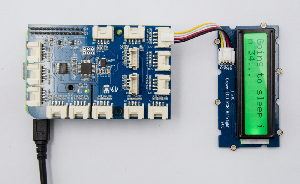
- Step 2. Connect Grove-LCD RGB Backlight to I2C port of Grove-Base Shield.
- Step 3. Plug Grove - Base Shield into Seeeduino.
- Step 4. Connect Seeeduino to PC via a USB cable.

If we don't have Grove Base Shield, We also can directly connect Grove-LCD RGB Backlight to Seeeduino as below.
| Seeeduino | Grove-LCD RGB Backlight |
|---|---|
| 5V | Red |
| GND | Black |
| SDA | White |
| SCL | Yellow |
Software
Step 1. Download the Grove-LCD RGB Backlight Library from Github.
Step 2. Refer How to install library to install library for Arduino.
Step 3. Here are 12 examples in the library as below.
- Autoscroll
- Blink
- Cursor
- CustomCharacter
- Display
- fade
- HelloWorld
- Scroll
- SerialDisplay
- setColor
- setCursor
- TextDirection
Step 4. Please follow below picture to select example HelloWorld and upload the arduino. If you do not know how to upload the code, please check how to upload code.

Here is the code of HelloWorld.ino.
#include <Wire.h>
#include "rgb_lcd.h"

rgb_lcd lcd;

const int colorR = 255;
const int colorG = 0;
const int colorB = 0;

void setup()
{
    // set up the LCD's number of columns and rows:
    lcd.begin(16, 2);

    lcd.setRGB(colorR, colorG, colorB);

    // Print a message to the LCD.
    lcd.print("hello, world!");

    delay(1000);
}

void loop()
{
    // set the cursor to column 0, line 1
    // (note: line 1 is the second row, since counting begins with 0):
    lcd.setCursor(0, 1);
    // print the number of seconds since reset:
    lcd.print(millis()/1000);

    delay(100);
}
- Step 4. We will see the hello world on LCD.
Play with Codecraft
Hardware
Step 1. Using a Grove cable connect Grove - LCD RGB Backlight to Seeeduino's I2C port. If you are using Arduino, please take advantage of a Base Shield.
Step 2. Link Seeedino/Arduino to your PC via an USB cable.
Software
Step 1. Open Codecraft, add Arduino support, and drag a main procedure to working area.
If this is your first time using Codecraft, see also [Guide for Codecraft using Arduino](https://wiki.seeedstudio.com/Guide_for_Codecraft_using_Arduino/).
Step 2. Drag blocks as picture below or open the cdc file which can be downloaded at the end of this page.

Upload the program to your Arduino/Seeeduino.
When the code finishes uploaded, you will see "hello, world!" and system running time displayed in the LCD.
Play With Raspberry Pi
Hardware
- Step 1. Prepare the below stuffs:
| Raspberry pi | GrovePi_Plus | Grove-LCD RGB Backlight |
|---|---|---|
|
|
|
| Get One Now | Get One Now | Get One Now |

- Step 2. Plug the GrovePi_Plus into Raspberry.
- Step 3. Connect Grove-LCD RGB Backlight to I2C port of GrovePi_Plus.
- Step 4. Connect the Raspberry to PC through USB cable.
Software
If you are using **Raspberry Pi with Raspberrypi OS >= Bullseye**, you have to use this command line **only with Python3**.
- Step 1. Follow Setting Software to configure the development environment.
- Step 2. Git clone the Github repository.
cd ~
git clone https://github.com/DexterInd/GrovePi.git
- Step 3. Excute below commands to use the Grove-LCD RGB Backlight to display.
cd ~/GrovePi/Software/Python/grove_rgb_lcd
python3 grove_rgb_lcd.py
Here is the grove_rgb_lcd.py code.
import time,sys

if sys.platform == 'uwp':
    import winrt_smbus as smbus
    bus = smbus.SMBus(1)
else:
    import smbus
    import RPi.GPIO as GPIO
    rev = GPIO.RPI_REVISION
    if rev == 2 or rev == 3:
        bus = smbus.SMBus(1)
    else:
        bus = smbus.SMBus(0)

# this device has two I2C addresses
DISPLAY_RGB_ADDR = 0x62
DISPLAY_TEXT_ADDR = 0x3e

# set backlight to (R,G,B) (values from 0..255 for each)
def setRGB(r,g,b):
    bus.write_byte_data(DISPLAY_RGB_ADDR,0,0)
    bus.write_byte_data(DISPLAY_RGB_ADDR,1,0)
    bus.write_byte_data(DISPLAY_RGB_ADDR,0x08,0xaa)
    bus.write_byte_data(DISPLAY_RGB_ADDR,4,r)
    bus.write_byte_data(DISPLAY_RGB_ADDR,3,g)
    bus.write_byte_data(DISPLAY_RGB_ADDR,2,b)

# send command to display (no need for external use)
def textCommand(cmd):
    bus.write_byte_data(DISPLAY_TEXT_ADDR,0x80,cmd)

# set display text \n for second line(or auto wrap)
def setText(text):
    textCommand(0x01) # clear display
    time.sleep(.05)
    textCommand(0x08 | 0x04) # display on, no cursor
    textCommand(0x28) # 2 lines
    time.sleep(.05)
    count = 0
    row = 0
    for c in text:
        if c == '\n' or count == 16:
            count = 0
            row += 1
            if row == 2:
                break
            textCommand(0xc0)
            if c == '\n':
                continue
        count += 1
        bus.write_byte_data(DISPLAY_TEXT_ADDR,0x40,ord(c))

#Update the display without erasing the display
def setText_norefresh(text):
    textCommand(0x02) # return home
    time.sleep(.05)
    textCommand(0x08 | 0x04) # display on, no cursor
    textCommand(0x28) # 2 lines
    time.sleep(.05)
    count = 0
    row = 0
    while len(text) < 32: #clears the rest of the screen
        text += ' '
    for c in text:
        if c == '\n' or count == 16:
            count = 0
            row += 1
            if row == 2:
                break
            textCommand(0xc0)
            if c == '\n':
                continue
        count += 1
        bus.write_byte_data(DISPLAY_TEXT_ADDR,0x40,ord(c))

# example code
if __name__=="__main__":
    setText("Hello world\nThis is an LCD test")
    setRGB(0,128,64)
    time.sleep(2)
    for c in range(0,255):
        setText_norefresh("Going to sleep in {}...".format(str(c)))
        setRGB(c,255-c,0)
        time.sleep(0.1)
    setRGB(0,255,0)
    setText("Bye bye, this should wrap onto next line")
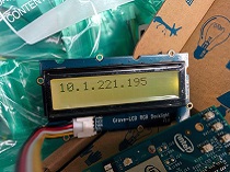
- Step 4. We will see the Grove-LCD RGB Backlight display as Going to sleep in 1...
FAQ
Q1: How to use multiple Grove-LCD RGB Backlight?
- A1: Please refer to Arduino Software I2C user guide.
Q2: How to use button to switch Grove RGB LCD to display different pages?
- A2: Here is the code.
#include <Wire.h>
#include "rgb_lcd.h"

rgb_lcd lcd;
const int switchPin = 2;
static int hits = 0;
int switchState = 0;
int prevSwitchState = 0;

void setup() {
    lcd.begin(16, 2);
    pinMode(switchPin,INPUT);
    Serial.begin(9600);
    lcd.setCursor(0, 0);
    lcd.print("Page 1");
}

void loop() {
  switchState = digitalRead(switchPin);
  Serial.print("switchState:");Serial.println(switchState);
  if (switchState != prevSwitchState) {
    if (switchState == HIGH) {
          hits = hits + 1;
          delay(10);
    }
  }

  Serial.print("hits:");Serial.println(hits);
  if(hits==1)
  {
    Serial.println("Page 1");
    lcd.clear();
    lcd.setCursor(0, 0);
    lcd.print("Page 1");
  }else
  if(hits==2)
  {
   Serial.println("Page 2");
    lcd.clear();
    lcd.setCursor(0, 0);
    lcd.print("Page 2");
  }else

  if(hits==3)
  {
   Serial.println("Page 3");
    lcd.clear();
    lcd.setCursor(0, 0);
    lcd.print("Page 3");
  }else

  if ( hits>=4)
  {
     hits = 0;
     Serial.println("couter is reset");
     Serial.println("Page 1");
     lcd.clear();
     lcd.setCursor(0, 0);
     lcd.print("Page 1");
  }
delay(500);
}
Resources
- [Library] Software Library
- [Document] Github page for this document
- [Codecraft] CDC File
- [Datasheet] PCA9633
- [Datasheet] JHD1313
Projects
Particle + Grove LCD RGB Backlight = Realtime Clock: Connect Grove LCD RGB Backlight to Particle using I2C to display time.
LCD RGB Grove module:
Tech Support & Product Discussion
Thank you for choosing our products! We are here to provide you with different support to ensure that your experience with our products is as smooth as possible. We offer several communication channels to cater to different preferences and needs.