Grove - Buzzer
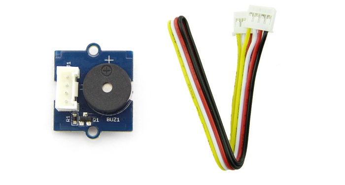
The Grove - Buzzer module has a piezo buzzer as the main component. The piezo can be connected to digital outputs, and will emit a tone when the output is HIGH. Alternatively, it can be connected to an analog pulse-width modulation output to generate various tones and effects.

Version
| Product Version | Changes | Released Date |
|---|---|---|
| Grove-Buzzer V1.0 | Initial | Nov 25 2010 |
| Grove-Buzzer V1.1 | Add S9013 Transistor | May 30 2014 |
Features
- Easy to use piezoelectric buzzer
- Uses Standard 4-pin Grove Cables to connect to other Grove modules such as - Grove Power Modules and Grove - Base Shield
More details about Grove modules please refer to [Grove System](https://wiki.seeedstudio.com/Grove_System/)
Specifications
| Items | Specification |
|---|---|
| Operating Voltage | 3.3V/5V |
| Sound Output | ≥85dB |
| Resonant Frequency | 2300±300Hz |
Platforms Supported
| Arduino | Raspberry Pi | |||
|---|---|---|---|---|
The platforms mentioned above as supported is/are an indication of the module's software or theoritical compatibility. We only provide software library or code examples for Arduino platform in most cases. It is not possible to provide software library / demo code for all possible MCU platforms. Hence, users have to write their own software library.
Getting Started
Play With Arduino
Hardware
- Step 1. Prepare the below stuffs:
| Seeeduino V4.2 | Base Shield | Grove - Buzzer |
|---|---|---|
 |  |  |
| Get ONE Now | Get ONE Now | Get ONE Now |
- Step 2. Connect Grove-Buzzer to port D6 of Grove-Base Shield.
- Step 3. Plug Grove - Base Shield into Seeeduino.
- Step 4. Connect Seeeduino to PC through a USB cable.

If we don't have Grove Base Shield, We also can directly connect Grove-buzzer to Seeeduino as below.
| Seeeduino | Grove-Buzzer |
|---|---|
| 5V | Red |
| GND | Black |
| Not Conencted | White |
| D6 | Yellow |
Software
- Step 1. Copy the code into Arduino IDE and upload.
void setup()
{
  pinMode(6, OUTPUT);
}

void loop()
{
  digitalWrite(6, HIGH);
  delay(1000);
  digitalWrite(6, LOW);
  delay(1000);
}
- Step 2. We will hear the buzzer on and off.
Play with Codecraft
Hardware
Step 1. Connect Grove - Buzzer to port D6 of a Base Shield.
Step 2. Plug the Base Shield to your Seeeduino/Arduino.
Step 3. Link Seeeduino/Arduino to your PC via an USB cable.
Software
Step 1. Open Codecraft, add Arduino support, and drag a main procedure to working area.
If this is your first time using Codecraft, see also [Guide for Codecraft using Arduino](https://wiki.seeedstudio.com/Guide_for_Codecraft_using_Arduino/).
Step 2. Drag blocks as picture below or open the cdc file which can be downloaded at the end of this page.

Upload the program to your Arduino/Seeeduino.
When the code finishes uploaded, you will hear the buzzer sound intermittently.
Play With Raspberry Pi (With Grove Base Hat for Raspberry Pi)
Hardware
- Step 1. Things used in this project:
| Raspberry pi | Grove Base Hat for RasPi | Grove - Buzzer |
|---|---|---|
 | 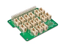 | |
| Get ONE Now | Get ONE Now | Get ONE Now |
- Step 2. Plug the Grove Base Hat into Raspberry Pi.
- Step 3. Connect the Grove Buzzer to PWM port of the Base Hat.
- Step 4. Connect the Raspberry Pi to PC through USB cable.

Software
If you are using **Raspberry Pi with Raspberrypi OS >= Bullseye**, you have to use this command line **only with Python3**.
- Step 1. Follow Setting Software to configure the development environment.
- Step 2. Download the source file by cloning the grove.py library.
cd ~
git clone https://github.com/Seeed-Studio/grove.py
- Step 3. Excute below command to run the code.
cd grove.py/grove
python3 grove_pwm_buzzer.py
Following is the grove_led.py code.
from __future__ import print_function

import time
from mraa import getGpioLookup
from upm import pyupm_buzzer as upmBuzzer

def main():
    print("Insert Grove-Buzzer to Grove-Base-Hat slot PWM[12 13 VCC GND]")

    # Grove Base Hat for Raspberry Pi
    #   PWM JST SLOT - PWM[12 13 VCC GND]
    pin = 12
    #
    # Create the buzzer object using RaspberryPi GPIO12
    mraa_pin = getGpioLookup("GPIO%d" % pin)
    buzzer = upmBuzzer.Buzzer(mraa_pin)

    chords = [upmBuzzer.BUZZER_DO, upmBuzzer.BUZZER_RE, upmBuzzer.BUZZER_MI,
              upmBuzzer.BUZZER_FA, upmBuzzer.BUZZER_SOL, upmBuzzer.BUZZER_LA,
              upmBuzzer.BUZZER_SI];

    # Print sensor name
    print(buzzer.name())

    # Play sound (DO, RE, MI, etc.), pausing for 0.1 seconds between notes
    for chord_ind in range (0,7):
        # play each note for a half second
        print(buzzer.playSound(chords[chord_ind], 500000))
        time.sleep(0.1)

    print("exiting application")

    # Delete the buzzer object
    del buzzer

if __name__ == '__main__':
    main()
If everything goes well, the buzzer will ring a few times and then stop, the program will automatically exit.
:::
Play With Raspberry Pi (with GrovePi_Plus)
Hardware
- Step 1. Prepare the below stuffs:
| Raspberry pi | GrovePi_Plus | Grove - Buzzer |
|---|---|---|
| 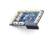 | |
| Get ONE Now | Get ONE Now | Get ONE Now |
- Step 2. Plug the GrovePi_Plus into Raspberry.
- Step 3. Connect Grove-Buzzer to D8 port of GrovePi_Plus.
- Step 4. Connect the Raspberry to PC through USB cable.

Software
If you are using **Raspberry Pi with Raspberrypi OS >= Bullseye**, you have to use this command line **only with Python3**.
:::
- Step 1. Follow Setting Software to configure the development environment.
- Step 2. Git clone the Github repository.
cd ~
git clone https://github.com/DexterInd/GrovePi.git
- Step 3. Excute below commands.
cd ~/GrovePi/Software/Python
python3 grove_buzzer.py
Here is the grove_buzzer.py code.
import time
import grovepi

# Connect the Grove Buzzer to digital port D8
# SIG,NC,VCC,GND
buzzer = 8

grovepi.pinMode(buzzer,"OUTPUT")

while True:
    try:
        # Buzz for 1 second
        grovepi.digitalWrite(buzzer,1)
        print ('start')
        time.sleep(1)

        # Stop buzzing for 1 second and repeat
        grovepi.digitalWrite(buzzer,0)
        print ('stop')
        time.sleep(1)

    except KeyboardInterrupt:
        grovepi.digitalWrite(buzzer,0)
        break
    except IOError:
        print ("Error")
- Step 4. We will hear the buzzer on and off.
pi@raspberrypi:~/GrovePi/Software/Python $ python3 grove_buzzer.py
start
stop
start
stop
Play With TI LaunchPad
Hardware
- This example shows how to use the Grove buzzer module to play melodies. It sends a square wave of the appropriate frequency to the buzzer, generating the corresponding tone.

Software
/*
  Buzzer
 The example use a buzzer to play melodies. It sends a square wave of the
 appropriate frequency to the buzzer, generating the corresponding tone.

 The circuit:
 * Buzzer attached to pin39 (J14 plug on Grove Base BoosterPack)
 * one side pin (either one) to ground
 * the other side pin to VCC
 * LED anode (long leg) attached to RED_LED
 * LED cathode (short leg) attached to ground

 * Note:
 This example code is in the public domain.

 https://www.seeedstudio.com/wiki/index.php?title=GROVE_-_Starter_Kit_v1.1b#Grove_-_Buzzer

*/

/* Macro Define */
#define BUZZER_PIN               39            /* sig pin of the buzzer */

int length = 15;         /* the number of notes */
char notes[] = "ccggaagffeeddc ";
int beats[] = { 1, 1, 1, 1, 1, 1, 2, 1, 1, 1, 1, 1, 1, 2, 4 };
int tempo = 300;

void setup()
{
    /* set buzzer pin as output */
    pinMode(BUZZER_PIN, OUTPUT);
}

void loop()
{
    for(int i = 0; i < length; i++) {
        if(notes[i] == ' ') {
            delay(beats[i] * tempo);
        } else {
            playNote(notes[i], beats[i] * tempo);
        }
        delay(tempo / 2);    /* delay between notes */
    }

}

/* play tone */
void playTone(int tone, int duration) {
    for (long i = 0; i < duration * 1000L; i += tone * 2) {
        digitalWrite(BUZZER_PIN, HIGH);
        delayMicroseconds(tone);
        digitalWrite(BUZZER_PIN, LOW);
        delayMicroseconds(tone);
    }
}

void playNote(char note, int duration) {
    char names[] = { 'c', 'd', 'e', 'f', 'g', 'a', 'b', 'C' };
    int tones[] = { 1915, 1700, 1519, 1432, 1275, 1136, 1014, 956 };

    // play the tone corresponding to the note name
    for (int i = 0; i < 8; i++) {
        if (names[i] == note) {
            playTone(tones[i], duration);
        }
    }
}
Grove - Buzzer Schematic Files v1.0
Grove - Buzzer Schematic Files v1.1
Resources
- [Eagle&PDF] Grove - Buzzer Schematic Files v1.1
- [Eagle&PDF] Grove - Buzzer Schematic Files v1.0
- [DataSheet] S9013datasheet
- [More Reading] Wooden Laser Gun
- [Codecraft] CDC File
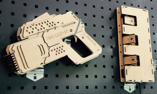
Inspired by OVERWATCH, we have made a very cool Wooden Laser Gun toy for fun these day!
The Wooden Laser Gun and the Gun Target are all based on an Arduino board called Seeeduino Lotus. The laser emitter on the Laser Gun is controlled to fire laser pulse to "activate" the Gun Target. And there are 3 light sensors on the Gun Target to detect the laser pulse. It seems very simple right? If you are interested in our project, please make one for yourself or your child! It's worth to spend one day DIY it as a Xmas present.
Proejcts
Grove - Introduction in a Buzzer: My first steps with the Grove 'plug & play' components. This is primarily a Buzzer.
Water Waste Monitor: Millions of gallons of water are wasted every year. Learn to conserve water with this project!
Buzzer Grove module:
Thank you for choosing our products! We are here to provide you with different support to ensure that your experience with our products is as smooth as possible. We offer several communication channels to cater to different preferences and needs.
Tech Support & Product Discussion
Thank you for choosing our products! We are here to provide you with different support to ensure that your experience with our products is as smooth as possible. We offer several communication channels to cater to different preferences and needs.